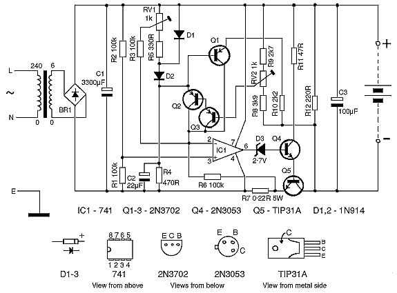
The circuit diagram in Fig. 1 is for a battery charger designed to charge any of the batteries in normal caving use. It is basically a 4.7V charger with a current limit of 2A which means that it will correctly charge any type of battery connected. It will not try to charge a battery accidentally connected in reverse. The design enables it to be used with a small transformer and so the complete charger can be made very small indeed - the prototype measured only 5x7x10cm. A specification is shown in Table 2. The current limit must not be set above 2A with the components listed in Table 1. With the voltage limit set at 4.7V it will charge 2-cell NiFes, NiCads, or lead-acid batteries. The voltage limit may have to be raised in order to charge 3-cell NiFes since an old and worn out NiFe may have an on-charge voltage approaching 2V per cell (though they are probably worth scrapping at this stage). For charging a 3-cell lead acid battery the voltage limit is adjusted to 6.9V. Various modifications are possible (see later) according to requirements.
This is straightforward if you have had some experience in soldering, otherwise you would be advised to practice first and to use a socket for the IC. Do not attempt to construct a very small unit unless you know what you're doing as it is very fiddly.

The power transistor (Q5) and the bridge rectifier should be bolted to small heatsinks and to the case. There must be adequate ventilation in the case for the transformer which also gets hot. Resistor R7 only dissipates about 1W but a 5W type is used since this will heat up less and so provide better current stability.
The prototype was built using a sub-minature 6V 2OVA transformer from R.S. Components Ltd. This transformer is smaller than many that are available but R.S. Components only distribute to educational and trade establishments. If you are set on minaturisation you will have to do some shopping around. (Failing this a local electrical shop mayorder it for you)
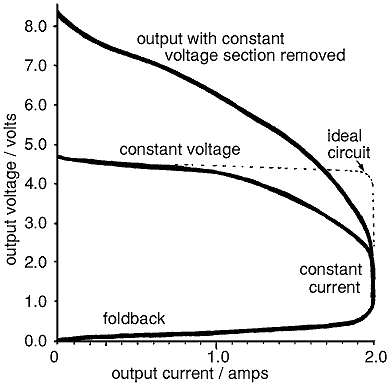
Setting up requires an accurate meter. Set RV1 midway and then use RV2 to adjust the open circuit output voltage to the required value. It may have to be reset when the unit has warmed up as it is temperature dependent to some extent. If constant voltage charging is not needed then RV2 can be set to give maximum voltage (or else omitted along with the associated components). When the voltage has been set RV1 is used to set the output current. A 1 ohm, 5W resistor is connected across the output, and RV1 adjusted until the output voltage gives a reading equal to the current required. (Tne resistor should be connected up after the charger has been switched on or it will go into 'foldback' operation and the output voltage will be almost zero). The current should be checked after the resistor has been allowed to cool down, and readjusted if neccessary. The output current must not be set above 2A with the components shown. Alternativly, setting RV1 about mid way will give a current of about 1A or the current can be set with an ammeter. If this is done a series resistor (or battery) must be used because the short circuit output current is nearly zero. If the output voltage is above 2.5V the maximum safe current is below 2A (see Fig.2). An important point to note is that an accurate meter must be used. The small 2A or 5A meters available in caving shops are extremely inaccurate and will not do (a 2A reading may mean a current of 2.5 to 3A!).
A meter can be connected in the output leads to give an indication of charging current which is useful when charging an Oldham. The charger is not particularly efficient at constant voltage charging due to the high (0.4 ohm) output resistance. It could be made much more efficient if an op. amp circuit were used instead of Q2 & Q3 but I haven't tried this yet.
Resistor RV1 can be replaced by a potentiometer to give a variable current output. If this is done R5 should be made a 470 ohm preset and used to adjust the maximum available current to a safe value (2A for the circuit shown).

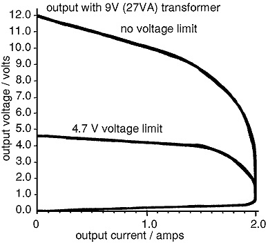
It will be noticed from Fig.2 that the output current available above about 2.5V is reduced. This is because of the low-voltage transformer used. If the charger is specifically for charging 3 cell lead-acid batteries or 3 cell NiFes then a higher current will be desirable. This can be obtained by replacing the transformer with a 9V 27VA type (see Fig.3). Resistor R8 should be decreased to about 1k to allow the voltage limit to be raised. If a higher voltage transformer is used and the charger used to charge NiFes or NiCads it will get rather hot unless a proper heatsink is used for the power transistor. If constant voltage charging is not required then RV2, Q2, Q3 and the associated components can be omitted. For a higher current output R5 or R7 should be reduced, and the bridge and Q5 changed for types that will withstand the current. C1 may also have to be increased substantially. It should be mentioned for those who want to experiment, that the maximum direct current available from a transformer is only about 0.6 of the alternating current rating. If you try to draw more than this the transformer will quickly get very hot. the value of C1 must not cause too great a loading on the bridge; if in doubt use discrete diodes as these are more able to withstand the current surges.

Resistors - all 0.25W except where stated
Ri 100k 5%
R2 100k 5%
R3 100k
R4 470
R5 330
R6 100k
R7 0.22 5W
R8 3.9k 5%
R9 2.7k
R1O 2.2k
R11 47 0.5W
R12 220
RV1 1k miniature preset
RV2 1k miniature preset
Capacitors
C1 3300µF 10V electrolytic
C2 22µF 10V electrolytic
C3 1OOµF 10V electrolytic
Semiconductors - similar types may be used
BR1 2A 50V bridge eg. SOO5 or 4x1N5000 diodes
D1 1N914
D2 1N914
D3 BZY88C 2V7
Q1 2N3702
Q2 2N3702
Q3 2N3702
Q4 2N3053
Q5 TIP31A
Transformer
T1 6V 2OVA type
Hardware
Mains cable (about 1.5m)
2A connecting wire (1m)
Extra-flexible 2A wire for output leads (1m)
Heatsink (eg 2 type TV4 or TVS for TO-126, TO-220 style devices)
2 Grommets
Nuts, Bolts
Veroboard
Croc clips or charging adapter
Meter (optional)
Case
Charging details
Charger automatically selects charging mode:
2-cell NiFe/NiCad 2.0A (variable)
3-cell NiFe* 1.6A max*
Oldham battery 4.7V (variable)
Reverse connection 25mA discharge
Charger switched off 25mA discharge
* with voltage section removed
The output characteristic is shown in Fig.2
Output resistance
constant current mode (at 2.5V) ~200
constant voltage mode (at 1A) ~0.4
Size: 5x10x7 cm
Weight: about 0.5kg