When taking photographs underground it is often necessary to use more than one flash gun. It is obviously desirable that the flashes are simultaneous, especially if the camera is hand held. The usual solution is to use an adaptor enabling the camera to take two flash leads. If the slave flash is some distance from the camera this involves the use of a long extension lead. There are two disadvantages with extension leads. Firstly, 20 feet or so of lead is inconvenient to carry. Secondly, electronic flash guns will not operate with a lead longer than about six feet (due to the capacitance and inductance of the lead). The trigger unit to be described uses a different method. It operates the 'slave' flashgun by detecting the light from the first gun.
Features of the unit are
1. Small size. (Prototype measures 5.5 x 4.5 x 3 cm.).
2. Long battery life. (quiescent current drain <1mA).
3. Operation at distances up to 25' from the other flash.
4. High imunity to operation from other light sources.
5. Indication that the unit has operated. (useful for checking operation).
6. Triggers slave within 1 microsec of the master flash.
7. Operates in bright sunlight as well as underground.
A disadvantage is that the unit cannot be used with a bulb flash as the triggering source (ie. the master flash unit must be electronic). The reason for this will be explained below.
The unit sets off one flash gun on receipt of the light from the other. However it is not sufficient to simply detect the presence of light otherwise it would operate whenever a caver shone his light in the general direction of the unit. The rising edge of the pulse of light from the flash is therefore detected and used to trigger the slave flash. To avoid operation due to a light passing across the unit (such as when the operator checks to see if the unit is still there), edges rising in less than about 1/1000 sec. must be ignored. This automatically excludes flash bulbs as the triggering source since the rise time of the light pulse from a flash bulb is about 1/100 sec. An electronic flash gun with a rise time of light output of about 50 microseconds is ideal as a triggering source.

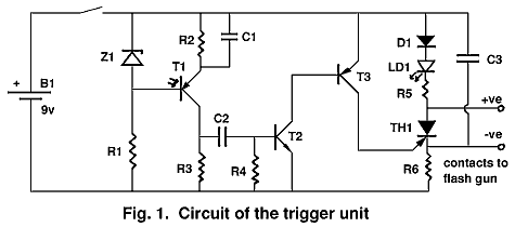
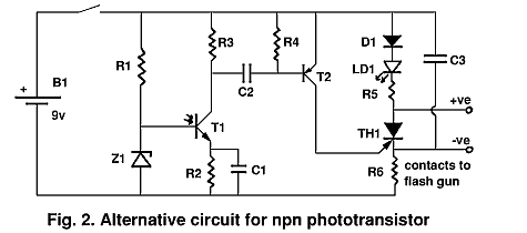
Details of the circuit operation will not be described since those who are interested can probably work out the mode of operation for themselves. The component list and the circuit diagram are for the unit which I use. See fig. 1. However I think operation can be improved and I give some changes in component values which should increase sensitivity and improve immunity to spurious operation. Fig 2 is a suggested circuit for use with an NPN photo transistor and should be as good as the version with the PNP photo-transistor. Both the modifications to the original circuit and to the circuit with the NPN photo-transistor are however untested.

Components for fig.1:
R1=15k, R2=47k, R3=6k8, R4=100k, R5=22k, R6=3k3, C1=0.1µF,
C2=0.68µF, C3=1µF, T1=OCP71 photo transistor, LD1=red
light-emitting diode, recommended current 20µA, T2=any npn silicon
small-signal transistor, T3= any pnp silicon small-signal transistor, Z1=5.1
volt zener diode, D1= any 200 volt diode, TH1=C106B 200 volt low gate current
thyristor, B1=9 volt PP3 battery.
Suggested components for improved version:
R3=10k, C1=0.068µF, C2=0.068µF, C3=0.1µF
Components for Fig. 2 (npn phototransistor version):
R1=15k, R2=68k, R3=15k, R4=560k, R2=22k, R6=3k3, C1=0.068µF,
C2=0.04µF, C3=0.1µF, T1=BP101, D1=200 volt diode, T2=pnp silicon
small-signal transistor, TH1=C106B, LD1= as above, Z1= 5.1v zener, B1=9V PP3
Geoff Wyss