This is perfectly satisfactory provided only one cell is to be charged at a time, and meets requirements 1 to 4.
| CUCC Home | ||
|---|---|---|
| Previous: The Batpondile |
CU 1975 Contents Page | Next: CU 1976 |
One of the minor drawbacks with rechargable electric lights is simply that they need recharging. A glance around the charging room at most caving huts will reveal a wide range of wierd, wonderful and lethal devices in use.
The requirements for a charger, in order of importance, can be summarised as follows.
It shall
Point No. 1, while perhaps obvious, is violated by large rack type chargers, some of which can deliver nasty shocks if touched. Metal cases should be earthed, and circuits correctly fused.
Indication of charging could be by meter, but as these do not stand up well to rough treatment a better solution is to use a light.
Often the need arises to charge a variable number of cells in series. This is facilitated if the charger delivers a current which is a constant, regardless of voltage.
The provision of variable current enables an only partially flattened cell to be 'topped up' overnight without gross overcharging.
Finally, the charger should not be excessively expensive. Bearing in mind that a cell costs at least £7-50, it is not unreasonable to spend £2-50 on a charger for one cell, and more for ones which will charge a greater number.
The remainder of this article outlines possible circuits which meet the requirements set out above, and gives details of some tested circuits.
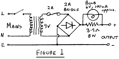
The simplest form of charger consists of a transformer, rectifier and limiting resistor. This can conveniently be combined with a low voltage light bulb to give indication of charging. A typical circuit is shown in Figure 1.
This is perfectly satisfactory provided only one cell is to be charged at
a time, and meets requirements 1 to 4.
It can be extended to give different currents by changing the resistor,
which could also allow the charging more than one cell. The drawback is that
it needs readjusting each time a change is made. It could be made to give an
approximately constant current by the 'brute force and ignorance' method of
increasing the transformer output and the value of the resistor.
Unfortunately the arrangement becomes less like a charger and more like an
electric fire!
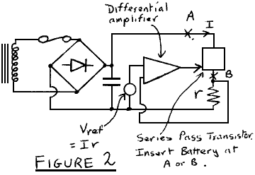
The ready availability of electronic components enables constant current
chargers to be constructed relatively easily. The circuits sense the output
current, which is compared with the required current, and the necessary
correction applied to a series pass element. This is indicated in Figure 2.
The simplest circuit of this kind consists essentially of a transistor
operated in the common base mode. The charging current is injected into the
emitter of the transistor by means of a constant reference voltage and
resistor, and the battery is inserted in the collector. In practice, a pair
of transistors is used. (Figure 3). The current is approximately 1.5/r amps
for the components shown.
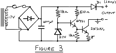
It is essential that the 2N3055 is efficiently heatsinked. It should be bolted directly to a heatsink of around 2°C/W, since, for an output of 1½ amps, it must dissipate about 25 W when the output is short-circuited. Indication of charging may be made by combining a light emitting diode with the reference diode, which is in effect shorted by resistor r when no load is connected (J.Heathcote). Alternatively, an LED and series resistor could be connected across r. Diode D1 protects against damage in the event of a power failure while a battery is connected.
As it stands, this circuit meets points 1 to 5, and will charge up to about 14 Volts. When one tries to extend the circuit to give variable current that some minor snags are met. Either r or the zener voltage is varied. The former requires a heavy duty switch, and the vagaries of contact resistance may lead to uncertainty in the charging current. The latter uses only low current switching. However, the voltage across r should be greater than one volt because of the large temperature coefficients of the emitter-base junctions and zener diode. Thus, while r drops 1 volt on the ½ amp range, it drops 3 volts on the 1½ amp setting. This limits the maximum output voltage and gives power dissipation problems in the resistor.
A better solution is to follow more closely the block diagram of Figure 2. If an integrated circuit amplifier is used, the voltage drop on R may be made much smaller, say ¼ Volt on the highest current range. There is now no objection to varying the reference voltage. A circuit of this type has been in use for several months (Figure 4). The low current setting has proved useful for charging small batteries such as those used in electronic flash guns. As a useful biproduct, when the charging current drops, the feedback loop goes out of balance which can be used to turn off an LED. This circuit will charge up to about 15 Volts at 1½ Amps, and meets all the requirements (1) to (6).
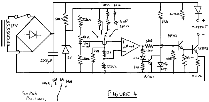
The output resistance has been calculated to be greater than 1 MegOhm, which has been confirmed by measurement. As before, the output transistor must have a large heatsink. A minor drawback is the large smoothing capacitors needed. It should be possible to reduce their size, by smoothing the supply to the control circuit only, which would be arranged to control the average charging current.
The constant current circuits described above suffer from the difficulty of large power dissipation when working into a short circuit. This section outlines techniques for overcoming this, although no satisfactory circuits have yet been developed.
At first sight a phase controlled thyristor circuit appears to satisfy the requirements. The thyristor is either off or on, and hopefully dissipates very little power. Unfortunately, at low battery voltages the charging current consists of short pulses of high amplitude, for which the RMS current is many times the mean value. This does not do the battery any good, and results in the transformer, rectifiers, and thyristor becoming very hot. The addition of a smoothing inductor, of say 2 Henry, eliminates this problem but is both expensive and bulky. However this is an attractive solution for high voltage, non-portable chargers.
A high frequency switching regulator technique could be used to reduce the size of the inductor. A D.C. supply, obtained in conventional manner from the mains supply, is switched on and off with a power transistor and the output is inductively smoothed. Experiments have been carried out in this field, but problems of slow transistor switching speed and of severe radio interference have yet to be solved.
As can be seen, there are many possible configurations for chargers, and there is plenty of scope for further development work.
JOHN HUNT
| CUCC Home | ||
|---|---|---|
| Previous: The Batpondile |
CU 1975 Contents Page | Next: CU 1976 |