Cambridge Underground 1972 pp 49-51
THE CAM BLOCK
The disadvantages of self-lining with a brake-block have already
been described in this Journal. It was with the tentative ideal of designing
a safer replacement for the brake-block that we started working on the
Cam-Block.
The criteria for this apparatus were as follows: that it should slide up a
rope with minimum friction, yet should jam instantaneously when a downward
load was applied. From this jammed position it had to be capable of being
converted easily into a descendeur, without the necessity of the caver
unkrabbing from it, thus making the whole operation failsafe. A further
possible criterion was that it should be capable of serving as a descendeur
in its own right, thereby eliminating one more item from the cavers
'Christmas Tree' of ironmongery.
As we were familiar with no existing piece of caving hardware suitable for
conversion, we armed ourselves with a pile of paper and thought afresh.
Eventually ideas crystallised and two designs evolved. One was of the
rotating cam type, the other of the falling arm type.
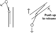
The first consisted of two pulley-sheaves, one fixed, the other free to
rotate about an eccentric axle.
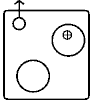 With the axle properly offset from the centre of the sheave, we hoped that
the apparatus could be pulled up the rope and that the weight of the sheave
With the axle properly offset from the centre of the sheave, we hoped that
the apparatus could be pulled up the rope and that the weight of the sheave
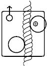 would counter balance the slight friction on the rope. When a downward force
was applied this sheave would be pulled down both by its own weight and by
the friction of the rope, and, being eccentric, would jam the rope against
the other, fixed, sheave. The whole issue would then topple gracefully over
to the abseiling position.
would counter balance the slight friction on the rope. When a downward force
was applied this sheave would be pulled down both by its own weight and by
the friction of the rope, and, being eccentric, would jam the rope against
the other, fixed, sheave. The whole issue would then topple gracefully over
to the abseiling position.
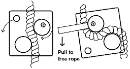 When a lever on the rotating sheave was moved, the rope would be unjammed,
and by controlling the rope with one hand one could abseil gently down. A
refinement would be a locking-pin to hold the rotating sheave in the
abseiling position, permitting the use of the contraption as an ordinary
descendeur.
When a lever on the rotating sheave was moved, the rope would be unjammed,
and by controlling the rope with one hand one could abseil gently down. A
refinement would be a locking-pin to hold the rotating sheave in the
abseiling position, permitting the use of the contraption as an ordinary
descendeur.
Though this seemed fine in principle it soon turned out to be unworkable
in practice. A couple of 2" diameter sheaves were turned in the University
Engineering Department, and a pair of steel plates cut to shape and drilled
with 1/8" holes at ½" centres (a sort of
custom-built Meccano!) With these bits and pieces and a variety of nuts and
bolts for good measure, we set about trying to find the ideal position for
the axle, both in the sheave and on the plates, so that the rope would run
freely, but jam when necessary. The ideal jamming distance (for No. 4 Nylon)
was found to be ¼" clearance between the sheaves, each of which was
slightly grooved around its circumference. By trial and error it was
established that the ideal offset position for the axle from the centre of
the rotating sheave was also ¼". The unsatisfactory nature of this
design became apparent when we tried to find a satisfactory point for
attaching a krab. Either the device jammed when climbing up, the sheave being
lifted round by friction, or the krab was in a position totally unsuitable
for abseiling. Furthermore, the clearance of the sheaves was so critical for
effective jamming that it would not have been possible to use the same
machine on both No.3 and No.4 rope. Reluctantly this design was abandoned
and it was back to the drawing-board.
The falling arm type appears rather more complicated. It started life
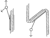 as a simple tube which, when pivoted, worked in much the same way as a
roulette descendeur.
as a simple tube which, when pivoted, worked in much the same way as a
roulette descendeur.
 As a further aid to jamming a form of lever was built into it which pressed
against the rope when a sudden downward force was exerted. This lever could
be quite easily released simply by twisting the whole device about the
lever's axle. Because the ideal position of the krab for sliding the
contraption up the rope and the ideal position for exerting leverage when the
caver falls did not coincide, a compromise was made with a slotted plate.
As a further aid to jamming a form of lever was built into it which pressed
against the rope when a sudden downward force was exerted. This lever could
be quite easily released simply by twisting the whole device about the
lever's axle. Because the ideal position of the krab for sliding the
contraption up the rope and the ideal position for exerting leverage when the
caver falls did not coincide, a compromise was made with a slotted plate.
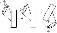 When climbing, the krab would remain in position 1; when a fall occurred it
would slide to position 2, exerting a greater leverage on the jamming-arm.
When the whole affair had pivoted the krab would slide back to I, in which
position a minimum twisting force would be necessary to convert the device
for abseiling. However this refinement was rejected as being unnecessary and
complex.
When climbing, the krab would remain in position 1; when a fall occurred it
would slide to position 2, exerting a greater leverage on the jamming-arm.
When the whole affair had pivoted the krab would slide back to I, in which
position a minimum twisting force would be necessary to convert the device
for abseiling. However this refinement was rejected as being unnecessary and
complex.
The latest stage which the falling arm type has reached is illustrated.
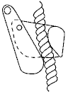 It will be seen to resemble somewhat the Hiebler prusiker, being very compact
and having approximately the same shape. One thing it does lack at the moment
is a device to unjam it for abseiling, but this is being worked on. When it
is perfected a lock will be included to make it suitable for use as a normal
descendeur.
It will be seen to resemble somewhat the Hiebler prusiker, being very compact
and having approximately the same shape. One thing it does lack at the moment
is a device to unjam it for abseiling, but this is being worked on. When it
is perfected a lock will be included to make it suitable for use as a normal
descendeur.
Tests have been highly satisfactory; no trouble has been experienced with
the arm trying to fall on the wrong side of the rope, and the Cam-Block
slides up quite readily, requiring a force of hardly more than its weight
alone. Also, because it only works with a shock loading it is
perfectly possible to line oneself down a ladder if not abseiling.
So far all our models have been built out of a mixture of light alloy and
steel for reasons of economy, but final models will be made entirely of
alloy. Things are not as easy as they seem, and the prototypes are undergoing
continual modification. However, prospects are bright, and a 'pre-production'
model should be ready soon, with Cam-Block No. 01 in use during the 1972
Summer Expedition.
GUY TALBOT